
INFORMATION ON THE MEASURING METHODS
INTRODUCTION SOUND POWER LEVEL LWA
In 1975 the European Commission proposed that noise radiated from machines would be represented by its sound power level in dB(A) as this unit is independent from factors as distance to the machine and can be used as an input data when calculating the distributions or immissions of the noise.
Of course it is necessary that the sound measured must represent the way the machine is working normally. This is accomplished by prescribing exactly how the machine is equipped, the way it is installed and the working cycle which it has to perform during the measurements.
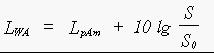
The sound power level is obtained by a combination of measurements and calculations the rules for which were eventually laid down in the European directive 79/113/CEE. The measurements are done under strict acoustical conditions to prevent the influence of weather or environment. From the measurement results (LpA) the average value LpAm is calculated. The value of this level and the size of the measurement surface of the microphone positions (usually a hemisphere) decide the sound power level LWA by adding the difference in decibels between the size of the measurement surface and a reference source of 1 m2.
In formula:
in which:
LWA = the A-weighted sound power level in dB(A);
LpAm = the mean of the A-weighted sound pressure levels at the measuring surface;
S = the size of the measuring surface in m2;
So = the reference surface (1 m2).
Assuming that the noise is radiated outward over a hemisphere the formula can be used reversibly also and from the sound power level the sound pressure level at a given distance can be calculated.
The surface of a hemisphere is calculated by 2pr2 ; r being the radius (=distance).
The difference between the sound power level and the sound pressure level becoming:
when:
r = 4 m 20 dB
r = 7.5 m 25.5 dB
r = 10 m 28 dB
There is a JavaScript where this form is implemented
Annex I of the Council Directive of 17 September 1984 on the approximation of the laws of the Member States relating to the permissible sound power level of compressors (84/533/EEC)
Annex I of the Council Directive of 17 September 1984 on the approximation of the laws of the Member States relating to the permissible sound power level of power generators (84/536/EEC)
Annex II of the Council Directive of 22 December 1986 on the approximation of the laws of the Member States relating to the permissible sound power level of hydraulic excavators, rope operated excavators, dozers, loaders and loader-excavators (86/662/EEC), as amended by the Commission Directive of 2 August 1989 on the adjustment to the technical progress (89/514/EEC)
The European Council directive 79/113/EEC of 19 December 1978 on the approximation of the Member-States relating to the measurement of the sound level of construction plant and equipment (OJ No L 33, 8.2.1979, p. 15.) lays down in its Annex I the method which should be used for establishing the acoustic criteria for machines used in the open air.
In the Netherlands this Annex is the base for all the national measuring methods for equipment.
As article 6.2. of the Annex, operation of the sound source during measurement, only supplies general conditions national experience dictates the working cycles used for each machine.
As specified by test code VAMIL Publication no.1.
Measuring Conditions
The mobile pump is tested in its standard version as described by the manufacturer.
The temperatures of the engine has to be within the operation limits as stated by the manufacturer.
The engine has to operate at the nominal speed.
Working cycle
The mobile pump has to operate at that combination of pressure and flow at which the pump requires the highest power.
For the measurement the measuring points 2, 4, 6, 8, 10 and 12 are used.
As specified by test code VAMIL Publication no. 2.
Measuring Conditions
The shredder is tested in its standard version as described by the manufacturer.
The temperature of the engine of the shredder has to be within the operation limits as stated by the manufacturer.
The sound levels are measured over the periods of time that the shredder performs the prescribed working cycle.
Working cycle
The working cycle exists out of the chipping of the prescribed piece of wood.
If the speed with which the wood can be inserted is variable the highest speed shall be used at which the wood can be inserted continuously and the working speed of the engine will be maintained.
The working speed of the engine is the RPM as mentioned in the technical documentation handed to the customer.
Wood for testing
The wood used for the test shall exist out of a piece of round pine-wood, sharpened at one end, with a length of at least 1.5 meter.
The diameter of the piece of wood shall be at least 50% but not more than 70% of the maximum diameter which the shredder can chip in accordance with the technical documentation handed to the customer. The largest diameter of the wood being the values mentioned in Table I.
| Permissible diameter according to manufacturer | |||
| Largest diameter wood | larger than | maximum | |
| 50 mm | 50 mm | 100 mm | |
| 70 mm | 100 mm | 140 mm | |
| 100 mm | 140 mm | 200 mm | |
| 140 mm | 200 mm | 280 mm | |
For the measurement the measuring points 2, 4, 6, 8, 10 and 12 are used.
As specified by test code VAMIL publication no. 3.
Measuring Conditions
The lift-truck is tested in its standard version as described by the manufacturer.
The temperatures of the engine and the hydraulic system of the lift-truck have to be within the operation limits as stated by the manufacturer.
The sound levels are measured over the periods of time that the lift-truck performs the prescribed working cycle.
Working cycle
The prescribed working cycle exists out of the phases a and b.
a. From standstill the lift-truck is driven with maximum acceleration over the run section of 10 m and the measuring section of 8 m.
If the lift-truck is equipped with a hand operated gearbox the highest transmission is chosen in which the lift-truck reaches within 10 m the maximum revolutions of the engine without exceeding the speed of 13 km/h.
The measuring section is that part of the measuring place that extents at the x-axle of the hemisphere 4 meters at both sides of the middle point.
b. The lift-truck lifts a load which equals 70% of the real capacity with maximum acceleration from minimum to maximum height.
The real capacity is the maximum load in kg which the lift-truck can lift and transport under working conditions as allowed by the manufacturer.
For the measurement the measuring points 2, 4, 6, 8, 10 and 12 are used.
Calculation of the sound power level LWA
For each phase the A-weighted sound power level LWA(a,b) of the lift-truck is calculated with the following formula:
1 in which:
LWA(a,b) = the A-weighted sound power level of each phase in dB;
LpAm(a,b) = the A-weighted sound pressure level in dB of each phase at the surface, as defined in 3.3
S = the size of the measuring surface in mý calculated in accordance with 8.3;
S0 = the reference surface (1 mý)
The sound power level LWA of the lift-truck is calculated with the formula:

2
As specified by test code VAMIL Publication no. 4.
Measuring Conditions
The mobile crane is tested in its standard version as described by the manufacturer.
The temperatures of the engine and the hydraulic system of the mobile crane have to be within the operation limits as stated by the manufacturer.
The sound levels are measured over the periods of time that the mobile crane performs the prescribed working cycle.
The mobile crane is installed such that the projection of the geometric middle point of the engine which drives the crane operation coincides with the middle point of the hemisphere. The driving direction of the under carriage is aimed at point 5 and the boom of the upper carriage is aimed at point 1.
If the driving direction of the under carriage is the same as the working direction of the boom, the mobile crane is aimed at point 1.
Working cycle
The prescribed working cycle exists out of the phases a, b, c and d.
a. Hoisting and lowering
The maximum rope speed is adjusted which is allowed to be used at the maximum rope force.
The crane is loaded with a load which creates 50% of the maximum rope force.
The phase starts with the maximum acceleration of the load and consists of the hoisting of the load and the immediately lowering till the starting position.
The length of the boom is chosen so that a full phase lasts 15 till 20 s.
b. Sluing
With the boom adjusted to an angle of 40-50ø with the measuring site and without load the upper carriage is slued 90ø to the left immediately followed by sluing back to the starting position.
A telescoping boom is at its minimum length.
c. Boom adjusting
The phase starts with raising the boom and exists out this raising immediately followed by the lowering of the boom to its original position. This movement is executed without load, at maximum speed and with maximum acceleration and deceleration. The phase has to last at least 20 s.
d. Telescoping
With the boom adjusted to an angle of 40-50ø with the measuring site and without load the fully withdrawn first part of the boom is extended to its full length and immediately withdrawn. The movement is executed at maximum speed.
The radius of the hemisphere is:
10 m if the length of the mobile crane is 4 m or less.
16 m if the length of the mobile crane is more than 4 m.
If the upper carriage is supplied with a driving engine, the length of the mobile crane is the length of the upper carriage without the boom.
If the upper carriage has no driving engine, the length of the mobile crane is the length of the under carriage.
For the measurement the measuring points 2, 4, 6, 8, 10 and 12 are used.
The highest of the sound power levels of all phases is the sound power level of the mobile crane.
As specified by test code VAMIL Publication no. 5.
Measuring Conditions
The reach truck is tested in its standard version as described by the manufacturer.
The temperatures of the engine and the hydraulic system of the reach truck have to be within the operation limits as stated by the manufacturer.
The sound levels are measured over the periods of time that the mobile crane performs the prescribed working cycle.
When performing phases b, c and d the reach truck is installed such that the projection of the geometric middle point of the engine which drives the lifting operation coincides with the middle point of the hemisphere. The driving direction of the under carriage is aimed at point 5 and the boom of the upper carriage is aimed at point 1.
If the driving direction of the under carriage is the same as the working direction of the boom, the reach truck is aimed at point 1.
If the reach truck is equipped with only one engine for both driving and crane operation, the reach truck is installed such that the middle point of the hemisphere is in the middle between the engine and the base of the boom.
Working cycle
The prescribed working cycle exists out of the phases a, b, c and d.
a. Driving
From standstill the reach truck is driven with maximum acceleration over the run section of 10 m and the measuring section of 8 m.
If the reach truck is equipped with a hand operated gearbox the highest transmission is chosen in which the reach truck reaches within 10 m the maximum revolutions of the engine without exceeding the speed of 13 km/h.
The measuring section is that part of the measuring place that extents at the x-axle of the hemisphere 4 meters at both sides of the middle point.
b. Sluing
With the boom adjusted to an angle of 40-50ø with the measuring site and without load the upper carriage is slued 90ø to the left immediately followed by sluing back to the starting position.
A telescoping boom is at its minimum length.
c. Boom adjusting
The phase starts with raising the boom and exists out this raising immediately followed by the lowering of the boom to its original position. This movement is executed without load, at maximum speed and with maximum acceleration and deceleration. The phase has to last at least 20 s.
d. Telescoping
With the boom adjusted to an angle of 40-50ø with the measuring site and without load the fully withdrawn first part of the boom is extended to its full length and immediately withdrawn. The movement is executed at maximum speed.
The radius of the hemisphere is:
10 m if the length of the reach truck is 4 m or less.
16 m if the length of the reach truck is more than 4 m.
If the upper carriage is supplied with a driving engine, the length of the reach truck is the length of the upper carriage without the boom.
If the upper carriage has no driving engine, the length of the reach truck is the length of the under carriage.
For the measurement the measuring points 2, 4, 6, 8, 10 and 12 are used.
The highest of the sound power levels of all phases is the sound power level of the mobile crane.
As specified by test code VAMIL Publication no.6.
Measuring Conditions
The hydraulic power pack is tested in its standard version as described by the manufacturer.
The temperature of the engine and the hydraulic system of the hydraulic power pack has to be within the operation limits as stated by the manufacturer.
The engine has to operate at the nominal speed.
Working cycle
The hydraulic power pack has to operate at that combination of pressure and flow at which the pump requires the highest power.
For the measurement the measuring points 2, 4, 6, 8, 10 and 12 are used.
As specified by test code VAMIL Publication no. 7.
Measuring conditions
The power sweeper has to be equipped for cleaning gutters (no under rollers) as described by the manufacturer. The temperatures of the engine and the hydraulic system of the power sweeper have to be within the operation limits as stated by the manufacturer. The projection on the ground of the middle point of the power sweeper is called "the reference point". The sound levels are measured over the periods of time that the power sweeper performs the prescribed working cycle.
The temperatures of the engine and the hydraulic system of the reach truck have to be within the operation limits as stated by the manufacturer.
The power sweeper is adjusted to its maximum capacity with the brush spinning at its maximum speed and, if installed, at maximum suction.
Working cycle
The measurement section AB is that part of the x-axis of the hemisphere which extents «Ö3 times the radius r at both sides of the middle point. The point A is situated in between the measuring points 2 and 4. With a constant speed, the lowest of the following speed, the power sweeper approaches point A over the x-axis:
- nominal speed
- 6 km/h
The working cycle starts at the moment the reference point of the power sweeper coincides with point A and ends at the moment the reference point coincides with point B.
For the measurement the measuring points 2, 4, 6, 8, 10 and 12 are used.
As specified by test code VAMIL Publication no. 8.
Measuring conditions
The aerial access platform is tested in its standard version as described by the manufacturer.
The temperatures of the engine and the hydraulic system of the aerial access platform have to be within the operation limits as stated by the manufacturer.
The sound levels are measured over the periods of time that the aerial access platform performs the prescribed working cycle.
Working cycle
If the aerial access platform is equipped with a telescoping boom the prescribed working cycle exists out of the phases a, b, c, and d.
If the aerial platform is not equipped with a telescoping boom the prescribed working cycle exisist out of the phases a and e.
a. Driving
From standstill the aerial access platform is driven with maximum acceleration over the run section of 10 m and the measuring section of 8 m.
If the aerial access platform is equipped with a hand operated gearbox the highest transmission is chosen in which the aerial access platform reaches within 10 m the maximum revolutions of the engine without exceeding the speed of 13 km/h.
The measuring section is that part of the measuring place that extents at the x-axle of the hemisphere 4 meters at both sides of the middle point.
b. Sluing
With the boom adjusted to an angle of 40-50ø with the measuring site and without load the upper carriage is slued 90ø to the left immediately followed by sluing back to the starting position.
A telescoping boom is at its minimum length.
c. Boom adjusting
The phase starts with raising the boom and exists out this raising immediately followed by the lowering of the boom to its original position. This movement is executed without load, at maximum speed and with maximum acceleration and deceleration. The phase has to last at least 20 s.
d. Telescoping
With the boom adjusted to an angle of 40-50ø with the measuring site and without load the fully withdrawn first part of the boom is extended to its full length and immediately withdrawn. The movement is executed at maximum speed.
e. Lifting
The phase starts with raising the platform and exists out this raising immediately followed by the lowering of the platform to its original position. This movement is executed without load, at maximum speed and with maximum acceleration and deceleration. The phase has to last at least 20 s.
The radius of the hemisphere is:
10 m if the length of the aerial access platform is 4 m or less.
- 16 m if the length of the aerial access platform is more than 4 m.
If the aerial access platform is equipped with an upper carriage, the length of the aerial access platform is the length of the upper carriage without the boom.
For the measurement the measuring points 2, 4, 6, 8, 10 and 12 are used.
The highest of the sound power levels of all phases is the sound power level of the aerial access platform.